
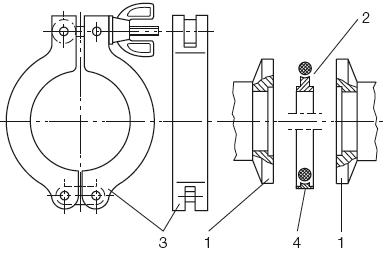
ISO-KF connection
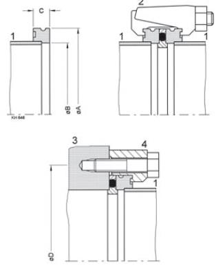
The ISO-KF connection (according to DIN 28 403 and ISO 2861) enables quick installation and replacement of components in the vacuum system. The system consists of two symmetrical ISO-KF flanges (1), a centering ring with O-ring gasket (2) and a clamping ring (or clamping ring) (3). High-vacuum-tight ISO-KF connections can be mounted without tools simply by placing the clamping ring over the flanges and turning the wing nut. In this way, the clamping ring presses on the conical parts of the flanges which, in turn, clamp the o-ring between the flat surfaces on the inside of the flanges.
Advantages of using the KF system:
- Fast, safe and reliable
- No tools needed
- Can handle pressures down to 10-7 mbar
- Can withstand pressures up to 2.5 Bar (with internal centering and 3-part
clamping rings) - Easy to disassemble and clean
- With metal seals, the system can withstand pressure down to 10-9 mbar
- With metal seals, the system can be baked up to 200 ° C
- With metal seals, the system is resistant to corrosion
- With metal seals, the system has a low degassing factor
- Many opportunities for transitions (between systems)
Size | Unit | A | B | C | D | Size | Unit | A |
DN 10 KF | mm | 30,0 | 12,2 | 12,2 | 45,0 | DN 10 KF | mm | 30,0 |
DN 16 KF | mm | 30,0 | 17,2 | 17,2 | 45,0 | DN 16 KF | mm | 30,0 |
DN 25 KF | mm | 40,0 | 26,2 | 26,2 | 55,0 | DN 25 KF | mm | 40,0 |
DN 40 KF | mm | 55,0 | 41,2 | 41,2 | 71,0 | DN 40 KF | mm | 55,0 |
DN 50 KF | mm | 75,0 | 52,4 | 52,4 | 91,0 | DN 50 KF | mm | 75,0 |
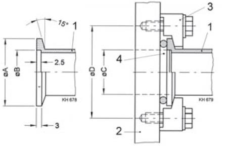
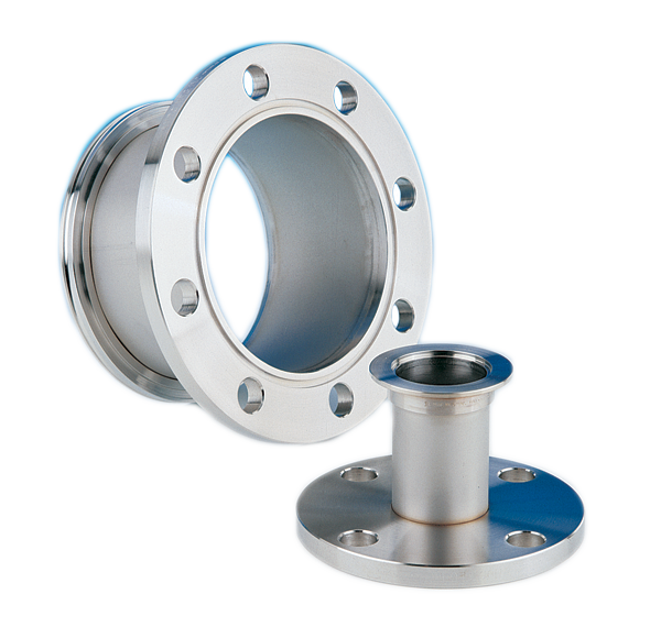
ISO-K connection
Just like the ISO-KF system, ISO-K has an o-ring that seals between the flanges. The system differs mostly in that the dimensions of ISO-K are larger and that it is not based on conical flanges.
However, the function is similar but is available in two versions.
The first one works in such a way that clamp couplings are mounted on the flanges’ heels and hooks in both flanges. the clamp couplings are then tightened with screws (the number is dimension dependent) which then presses the o-ring against the flat flange surfaces.
The second embodiment requires a flange with threaded boreholes on one flange and a bevel bevel on the other. The similarity is that a clutch fitting is mounted on the flange with the lug and then screws in the bolt in the threaded bore of the other flange. This version is called ISO-F.
Benefits of using the ISO-K (/ -F) system:
- Quick to install
- Safe and reliable
- Can be rotated in any orientation
- Easy to disassemble and clean
- Withstands pressure down to 10-7 mbar with o-rings (10-9 with metal seals)
- Easy transitions to other systems
- Flexible components for vibrating equipment are available
Size | Unit | A | B | C | Number of clamps | D | Screw measure | Number of claws |
DN 63 ISO-K | mm | 95 | 70 | 12 | 4 | 110 | M8x35 | 4 |
DN 100 ISO-K | mm | 130 | 102 | 12 | 4 | 145 | M8x35 | 8 |
DN 160 ISO-K | mm | 180 | 153 | 12 | 4 | 200 | M10x35 | 8 |
DN 200 ISO-K | mm | 240 | 213 | 12 | 6 | 260 | M10x35 | 12 |
DN 250 ISO-K | mm | 290 | 261 | 12 | 6 | 310 | M10x35 | 12 |
DN 320 ISO-K | mm | 370 | 318 | 17 | 8 | 395 | M12x50 | 12 |
DN 400 ISO-K | mm | 450 | 400 | 17 | 8 | 480 | M12x50 | 16 |
DN 500 ISO-K | mm | 550 | 501 | 17 | 12 | 580 | M12x50 | 16 |
DN 630 ISO-K | mm | 690 | 651 | 22 | 12 | 720 | M12x55 | 20 |
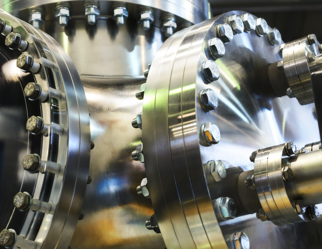
CF-couplings
CF couplings are generally used in high vacuum and ultra high vacuum. It is not as quick to replace as ISO-K / KF but has other advantages instead. The coupling is very common in various applications within HV and UHV and many times a standard for systems where the leakage has to be minimal.
The sizes available commercially span DN16-DN300. Since the application area is HV and UHV, all parts should be very clean and stored except for the risk of contamination from particles or dirt.
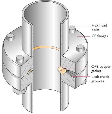
Sealing principle
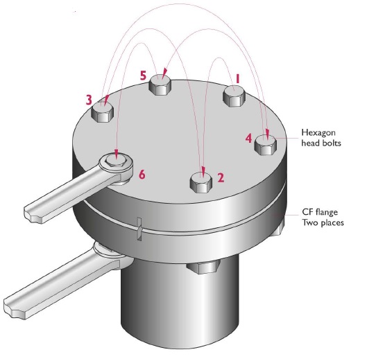
Between two flanges a metal seal (usually copper) is placed. As the bolts are tightened (crosswise), the knife edge of the flanges cuts into the metal seal and gradually seals the entire coupling joint. The bolts are advantageously pulled with a torque wrench. The torque depends on the bay bolt size used (indirect flange size) between 9 Nm-45Nm (see catalog for more information).
Installation:
Place an OFE copper gasket against the blade edge with clean lint-free gloves. Secure the two flanges with a bolt. The first bolt must ensure that the gasket is stationary and does not move during the remainder of the assembly and support the gasket from falling out of position. With the gasket in place, align all holes in each location, leak test grooves should be in the same place. Then install the bolts into bolts and tighten. Trays are usually used on the nut side of the fastener.
”Anti-seize” floating locking is recommended for attaching all stainless steel hardware. This is especially true with holes or blind holes. Retighten all bolts and nut. The tightening process must be done gradually from a quarter to a half step, in an alternating cross pattern. Continue until the desired torque rating has been reached. In this way, a reliable seal with an even gasket ensures compression and deformation.
Contact us
Datavägen 57B, 436 32 Askim, Sverige
Svederusgatan 1, 754 50 Uppsala, Sverige
Svederusgatan 1, 754 50 Uppsala, Sverige